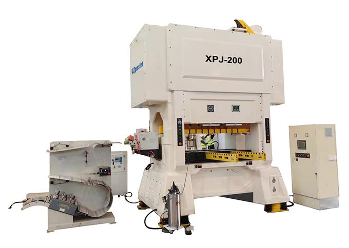
Product Features :
HIGH PRECISION STABILITY AND RELIABILITY
High steel alloy casting frame structure (with the most suitable for the frame designed by computer anal-ysis), processed by the internal stress elimination pro-cess, and further improving the high rigidity frame,achieving low noise and low vibration, and improving service life of the die.
Standard configuration :
■ Electric model height adjustment .
■ Die height display precision 0.01mm .
■ Inching positioning device .
■ The computer can memorize data of 30 sets of mold .
■ Three groups of batch control .
■ Two groups of feed error detection .
■ Linked/single action, with 0° and 90° positioning function .
■ Host forward/reverse device .
■ Hydraulic slide lock device .
■ Lubricating oil cooling cycle machine .
■ Italian OMPI integrated clutch brake .
■ Independent electric control cabinet .
■ Tooling box .
■ Work area light .
■ Main motor frequency converting control .
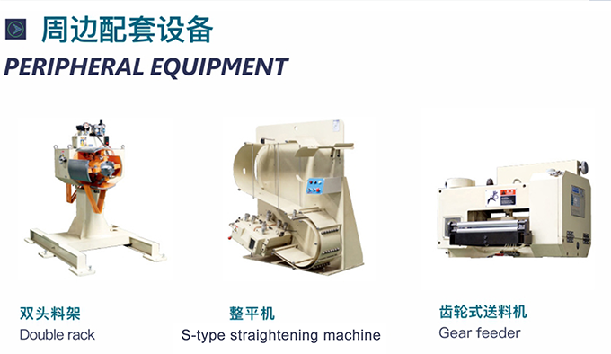
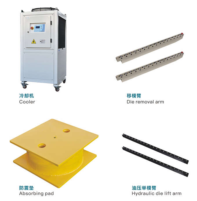
Optional configuration :
■ Bottom dead center precision detector .
■ Quick die clampers .
■ Hydraulic die lifting device .
■ High speed feeder .
■ Double head decoiler .
■ Leveling machine .
■ Hydraulic anti-viberatioin cushion .
■ Punching controller .
■ Front and rear safety protect door.
* Provide Customized Personalized Service
|
XPJ- 60ton ~200ton |
|
Model |
Unit |
XPJ-60 |
XPJ-80 | XPJ-125 | XPJ-150 | XPJ-200 |
| Tonnage | Ton | 60 | 80 | 125 | 150 | 200 |
| Travel | mm | 30 | 30 | 30 | 30 | 30 |
| Number of stokes per minute | s.p.m | 200-800 | 200-700 | 150-700 | 150- 600 | 150-600 |
| Lower table size | mm | 950x650 | 1100x750 | 1200x850 | 1400x850 | 1700x950 |
| Blanking hole | mm | 700x125 | 800x150 | 1000x200 | 1200x200 | 1300x250 |
| Sliding block area | mm | 950x420 | 1100x500 | 1200x600 | 1400x600 | 1700x700 |
| Die height adjustment stroke | mm | 300-350 | 330-380 | 360-410 | 360- 410 | 370-420 |
| Die height adjustment motor | kw | 0.4 | 0.75 | 0.75 | 0.75 | 1.5 |
| Feeding line height | mm | 160 | 175±50 | 195±50 | 195±50 | 200±50 |
| Main motor | kw | 19 | 22 | 30 | 37 | 45 |
|
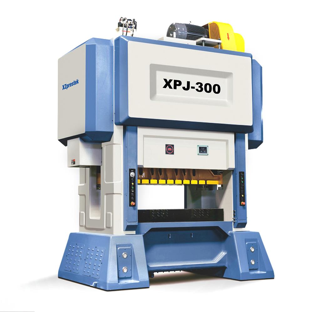
XPJ- 220ton~450 ton |
|
Model |
Unit |
XPJ-220 | XPJ-300 | XPJ-400 | XPJ-150 | XPJ-450 |
| Tonnage | Ton | 220 | 300 | 350 | 400 | 450 |
| Travel | mm | 30 | 30 | 30 | 30-50 | 30-50 |
| Number of stokes per minute | s.p.m | 150-600 | 150- 400 | 150- 350 | 150-350 | 150-300 |
| Lower table size | mm | 1900x1000 | 2200x1000 | 2400x1000 | 2800x1200 | 3000x1200 |
| Blanking hole | mm | 1400x300 | 2000x300 | 2200x300 | 2200x400 | 2500x400 |
| Sliding block area | mm | 1900x750 | 2200x900 | 2400x900 | 2800x1100 | 3000x1100 |
| Die height adjustment stroke | mm | 370-420 | 400 -450 | 400- 450 | 420- 480 | 450-500 |
| Die height adjustment motor | kw | 1.5 | 2.2 | 2.2 | 3.7 | 3.7 |
| Feeding line height | mm | 200±50 | 210±50 | 210±50 | 220±50 | 270±50 |
| Main motor | kw | 45 | 55 | 55 | 75 | 75 |